Guitar amp conversions of old PA amplifiers are very fun projects to take on. There’s so many different amplifiers, that each one is unique. It would be easy to force any design into a PA chassis, but the best conversions let the chassis dictate the design. For example, when I first received this PA amplifier for conversion, I figured it would be a quick job. While the conversion itself only took about 10 hours, the planning that went into this took quite a bit longer.
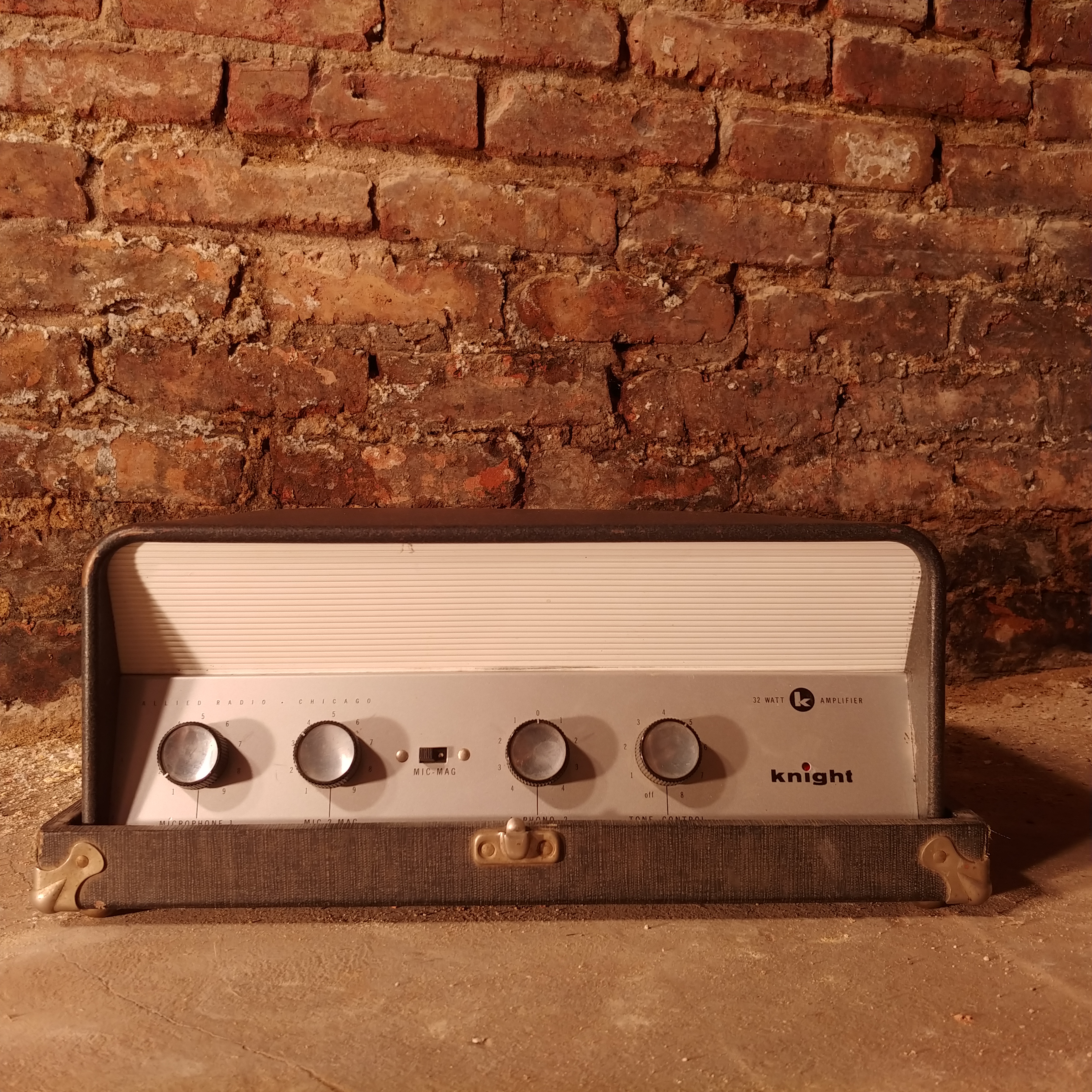
Initially, I saw 4 controls, 2x 6L6s and 2.5x 12AX7s (a 6AV6 is ½ of a 12AX7) and thought I’d make a modified Fender® 5E3 (1955-1960 Deluxe®) with 35 watt output. Incidentally, this is would be very close to a Fender® 5E5 (1955-1960 Pro®). But that leaves an extra unused gain stage on the table. So I started planning on a gain boost for the Deluxe® bright channel. The extra control would be a gain control, and the toggle switch would bypass the extra gain stage. But this amplifier had different plans.
Two of the controls had a switch on them. One was used as a power switch before, so that’s a no-brainer. However, what should the other switch be used for? Additionally, one of the controls was a center-tapped pot. It was originally used to control the volume of two different record players. Rotate counterclockwise from center to turn up player 1, or rotate clockwise from center to turn up player 2. Going back to center turned off both. If I tried to use this for the Deluxe® circuit, the magic interaction between channels would be lost! So it was back to the drawing board.
I noticed the amplifier had an additional 8 pin tube socket. It was used to power the motors on the record players, rather than for an additional tube. But I thought, this would be a great spot to add another tube. How about a 6SL7? This gave me a total of 7 gain stages to play with! Now we’re talking! I ended up with a design that used all 4 knobs and all 3 switches, to make a 2.5 channel amplifier!
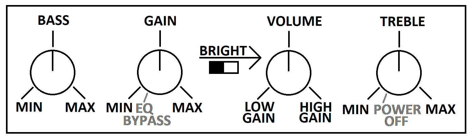
The leftmost knob is the bass knob. The next one over is the gain knob. At minimum, the pre-amp is very clean. Turn it all the way over to max for 35 dB of pre-amp boost! When turned down passed minimum, the EQ is bypassed for a very raw straightforward tone. It’s just you and your guitar. It’s as close as plugging straight into the speaker as you can get! With the EQ bypassed, you can get some great power tube overdrive by cranking the volume towards Low Gain. The switch in the middle is the bright switch, enabled when pushed to the right. This switch works with the volume control to provide a boost to the treble at lower volumes. It works even with the EQ bypassed. The volume knob is unlike any other amplifier you may have used. When pointed straight up, the amplifier is muted. Rotate it towards Low Gain, and you increase the volume of the low gain channel. Rotate it towards High Gain and you increase the volume of the high gain channel. This works no matter what the gain control is set to. Putting the gain on EQ Bypass and rotating the volume towards High Gain gives you a raw pre-amp sound with a mild overdrive. The bright switch is tied to the low gain side of this knob. When on the low gain side of the knob, it works like any other bright switch you may have used in the past. However, when you are on the high gain side of the knob, it adds in treble from the low gain channel! The result is a dynamic and clean high end, with a sustaining distorted low end. It’s a very sweet tone, and unlike anything you may have heard before! The rightmost knob is the treble control. When turned down passed minimum, the amplifier turns off.
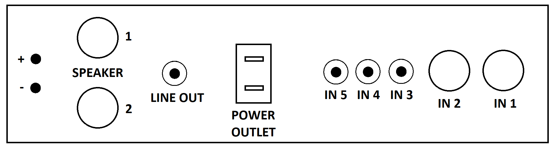
The ¼” inputs are on the back side, with two inputs set up like the typical Fender® inputs. #1 is the primary input with #2 being a little softer and darker. There are also three RCA inputs with similar characteristics to the #2 ¼” input. There are two ¼” speaker outputs and a “Tape Output” that is set up as a line-out. The impedance selector is unique to this PA amplifier, in that it has a wire that must be put into the correct impedance slot. This amplifier can run 4, 8, 16, 156, 250 and 500 ohm speakers! The 156 ohm is also usable as a 70V output, in case you want to run your cab several thousand feet away.
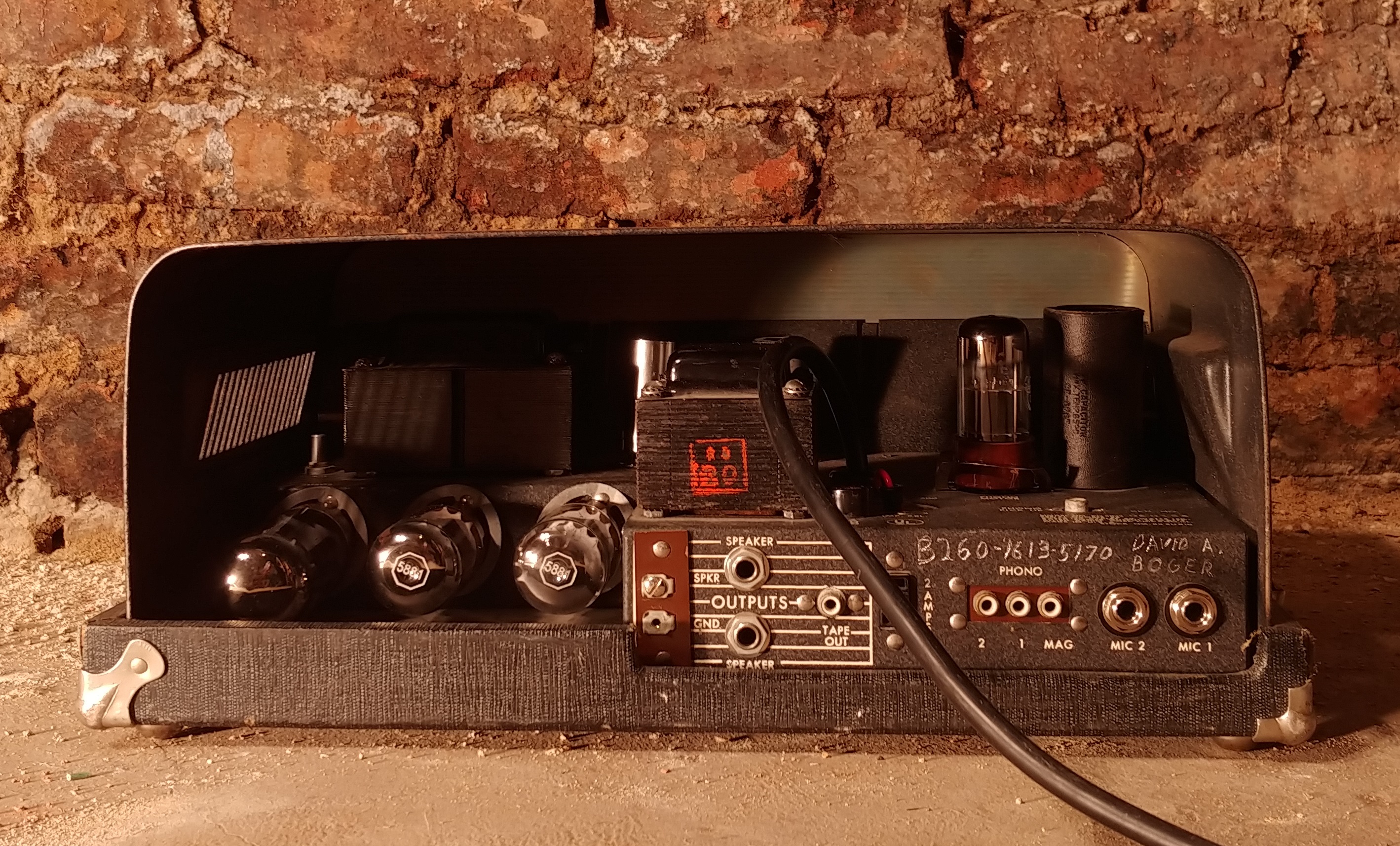
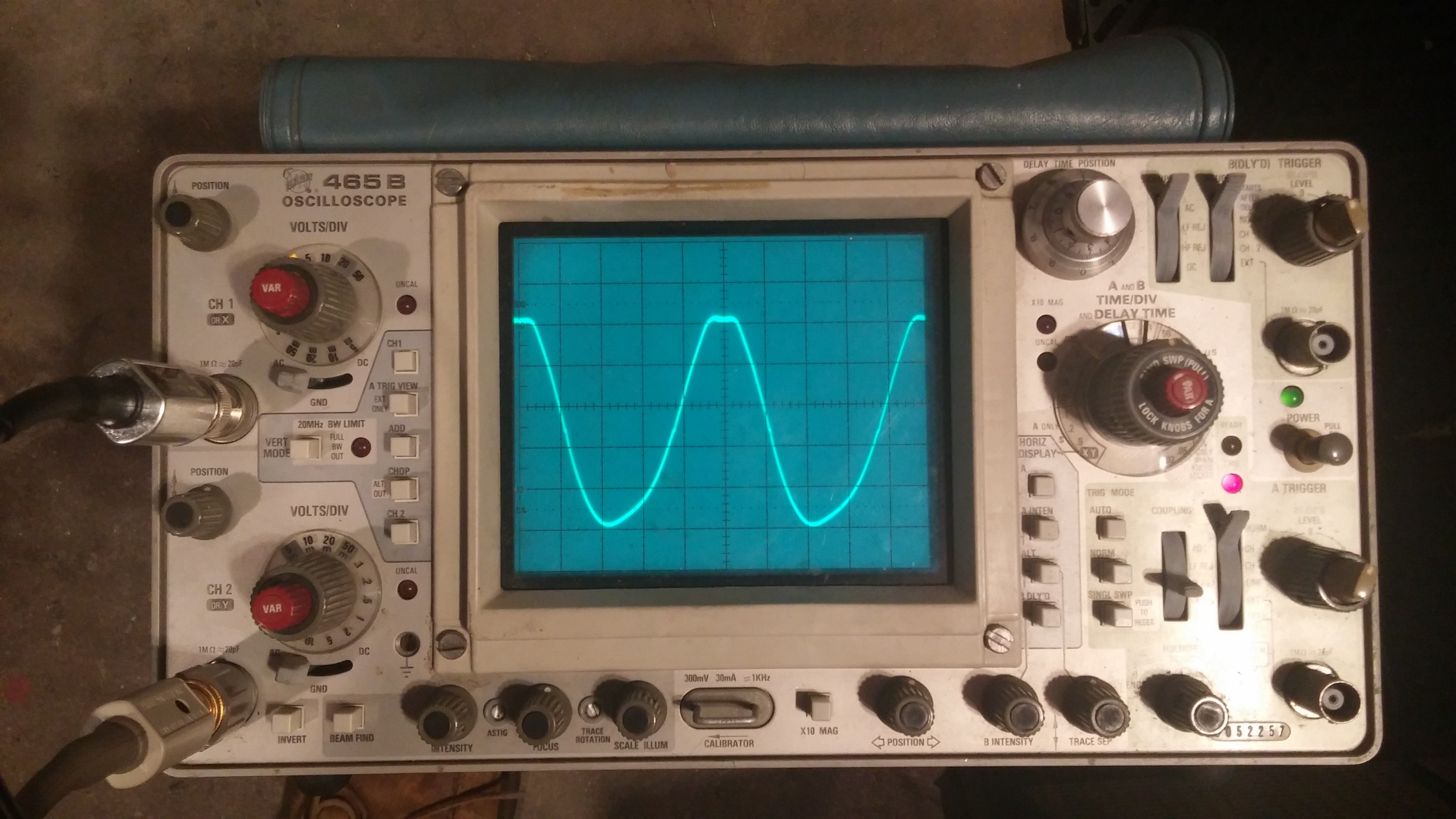
The tubes used are two 12AX7s, one 6SL7, one 6AV6, two 6L6s and one 5U4. Power output is 32 watts. The power amp can be driven to overdrive with as little as 45mV (-30dBV) at maximum volume. This is well within the range of a single coil pickup. This compares to 120mV (-21dBV) for a Deluxe®. With the gain control maxed, the low gain channel overdrives at 45mV (-30dBV) for a mild overdrive. The high gain channel is overdriven at 0.8mV (-65dBV). This compares to 0.34mV (-72dBV) of a Soldano® SLO®. While it has very high gain capabilities, this amplifier is designed around low gain playing. The tube rectifier provides a sweet sustain to your playing.
More pictures and a sound clip are available at https://www.instagram.com/jdpamps/.
For the recording, I used a Les Paul copy straight into the amplifier. The speaker was a single 12″ Jensen Electric Lightning. Recording mic was my phone, an LG V30. Unfortunately, the phone added a bit of compression, so the volume difference between clean and cranked cannot be appreciated in this video.