
Check out my Merch store!


I was recently repairing an old amplifier that contained a specialized IC. The amplifier as a whole worked well, but had some problems with the effects switching. I tracked it down to a defective IC, the TL604 / SN99661. Unfortunately, this IC had been obsolete since sometime in the 1990s. Peavey once made a kit that allowed the use of another current production IC, but that kit has also gone obsolete. While the kit can still be found, it was MUCH larger than the original part, requiring custom work to install. That’s assuming there’s room inside the amp.
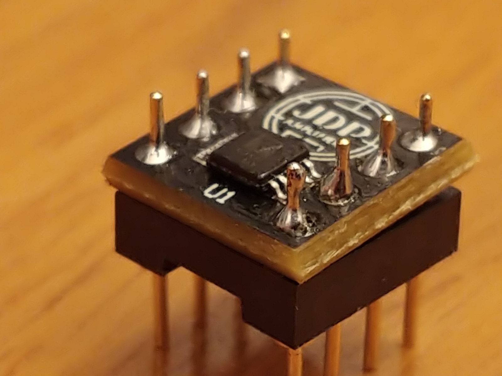
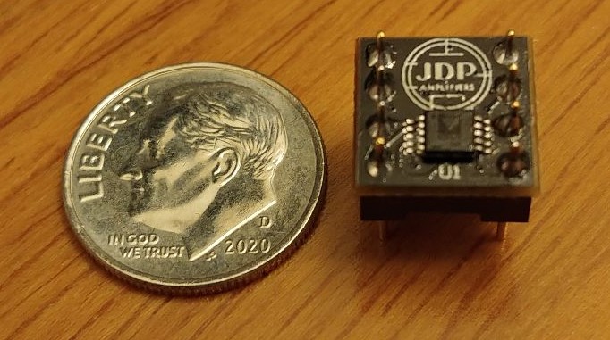
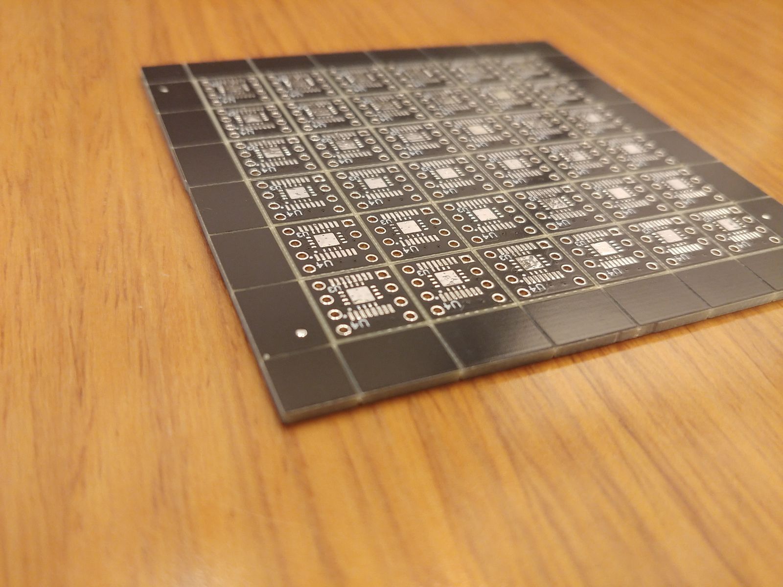
Rather than waiting for another solution to appear, and not satisfied with scrapping another otherwise good amplifier, I decided to make my own replacement solution. I found a modern part that would do the task. With the magic of miniaturization, the new IC is so small that it can fit within the space of the original IC! In order to make this as future resistant as possible, I designed the PCB to accommodate two different package styles of the same new IC. Not only that, I included space to put an entirely different modern IC on the other side of the board (not visible). This too has two different package styles. In all, there are now 4 modern ICs that will fill the role of this long unobtanium IC. I call it the TL604JDP.
The TL604JDP brings new life to old Peavey and Gallien-Krueger amplifiers by providing an alternative to “Obsolete” and “unavailable”. Below is my adaptor board in place, sitting next to the failed TL604 that I removed. It is plug and play with this adaptor! Here the TL604JDP is giving new life to the phaser circuit on a Peavey Classic VT-212.

Guitar amp conversions of old PA amplifiers are very fun projects to take on. There’s so many different amplifiers, that each one is unique. It would be easy to force any design into a PA chassis, but the best conversions let the chassis dictate the design. For example, when I first received this PA amplifier for conversion, I figured it would be a quick job. While the conversion itself only took about 10 hours, the planning that went into this took quite a bit longer.
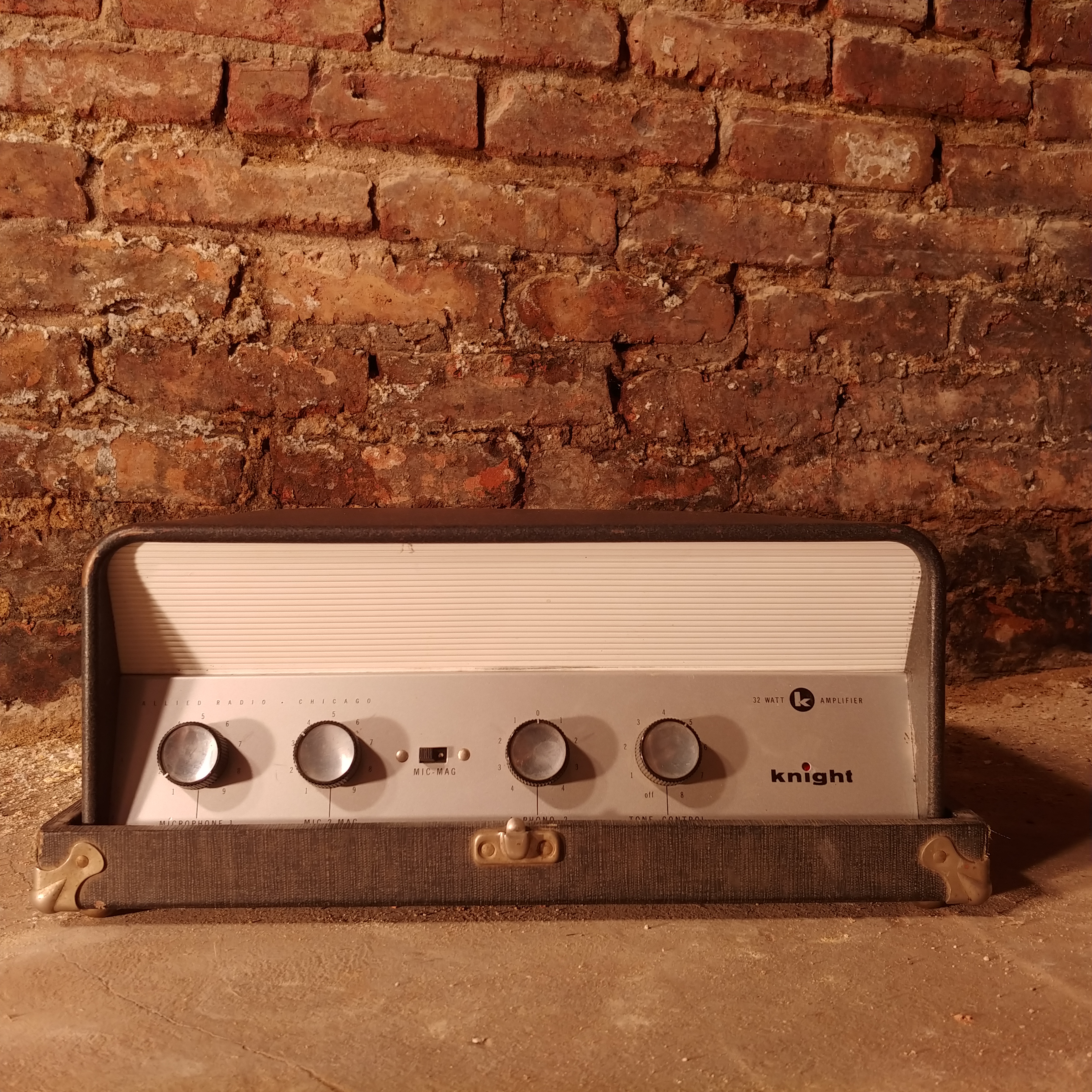
Initially, I saw 4 controls, 2x 6L6s and 2.5x 12AX7s (a 6AV6 is ½ of a 12AX7) and thought I’d make a modified Fender® 5E3 (1955-1960 Deluxe®) with 35 watt output. Incidentally, this is would be very close to a Fender® 5E5 (1955-1960 Pro®). But that leaves an extra unused gain stage on the table. So I started planning on a gain boost for the Deluxe® bright channel. The extra control would be a gain control, and the toggle switch would bypass the extra gain stage. But this amplifier had different plans.
Two of the controls had a switch on them. One was used as a power switch before, so that’s a no-brainer. However, what should the other switch be used for? Additionally, one of the controls was a center-tapped pot. It was originally used to control the volume of two different record players. Rotate counterclockwise from center to turn up player 1, or rotate clockwise from center to turn up player 2. Going back to center turned off both. If I tried to use this for the Deluxe® circuit, the magic interaction between channels would be lost! So it was back to the drawing board.
I noticed the amplifier had an additional 8 pin tube socket. It was used to power the motors on the record players, rather than for an additional tube. But I thought, this would be a great spot to add another tube. How about a 6SL7? This gave me a total of 7 gain stages to play with! Now we’re talking! I ended up with a design that used all 4 knobs and all 3 switches, to make a 2.5 channel amplifier!
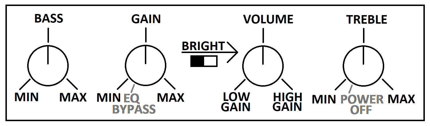
The leftmost knob is the bass knob. The next one over is the gain knob. At minimum, the pre-amp is very clean. Turn it all the way over to max for 35 dB of pre-amp boost! When turned down passed minimum, the EQ is bypassed for a very raw straightforward tone. It’s just you and your guitar. It’s as close as plugging straight into the speaker as you can get! With the EQ bypassed, you can get some great power tube overdrive by cranking the volume towards Low Gain. The switch in the middle is the bright switch, enabled when pushed to the right. This switch works with the volume control to provide a boost to the treble at lower volumes. It works even with the EQ bypassed. The volume knob is unlike any other amplifier you may have used. When pointed straight up, the amplifier is muted. Rotate it towards Low Gain, and you increase the volume of the low gain channel. Rotate it towards High Gain and you increase the volume of the high gain channel. This works no matter what the gain control is set to. Putting the gain on EQ Bypass and rotating the volume towards High Gain gives you a raw pre-amp sound with a mild overdrive. The bright switch is tied to the low gain side of this knob. When on the low gain side of the knob, it works like any other bright switch you may have used in the past. However, when you are on the high gain side of the knob, it adds in treble from the low gain channel! The result is a dynamic and clean high end, with a sustaining distorted low end. It’s a very sweet tone, and unlike anything you may have heard before! The rightmost knob is the treble control. When turned down passed minimum, the amplifier turns off.
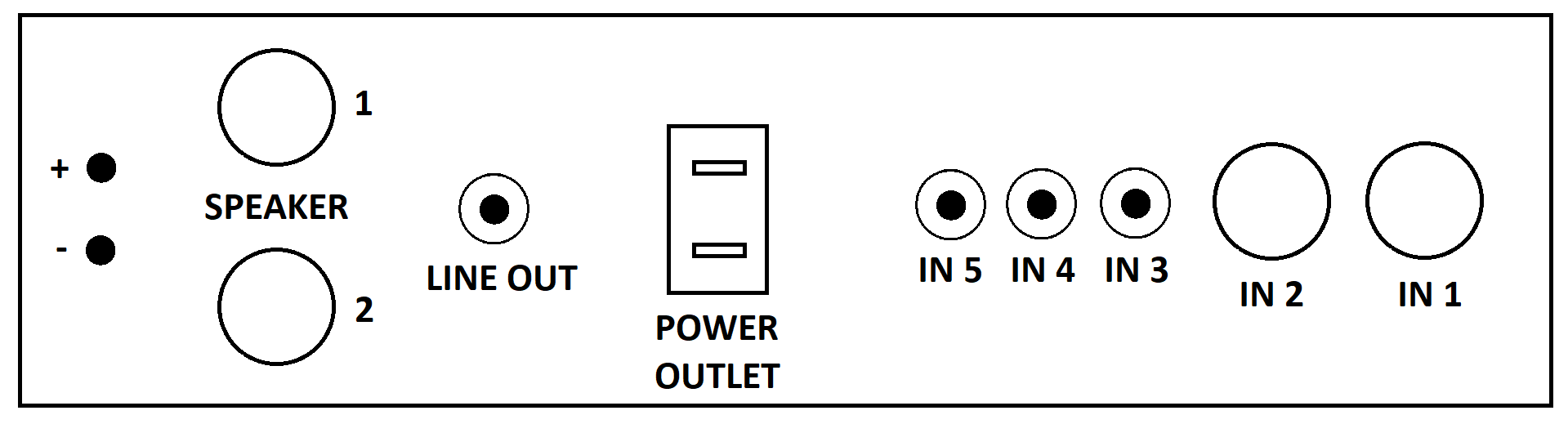
The ¼” inputs are on the back side, with two inputs set up like the typical Fender® inputs. #1 is the primary input with #2 being a little softer and darker. There are also three RCA inputs with similar characteristics to the #2 ¼” input. There are two ¼” speaker outputs and a “Tape Output” that is set up as a line-out. The impedance selector is unique to this PA amplifier, in that it has a wire that must be put into the correct impedance slot. This amplifier can run 4, 8, 16, 156, 250 and 500 ohm speakers! The 156 ohm is also usable as a 70V output, in case you want to run your cab several thousand feet away.
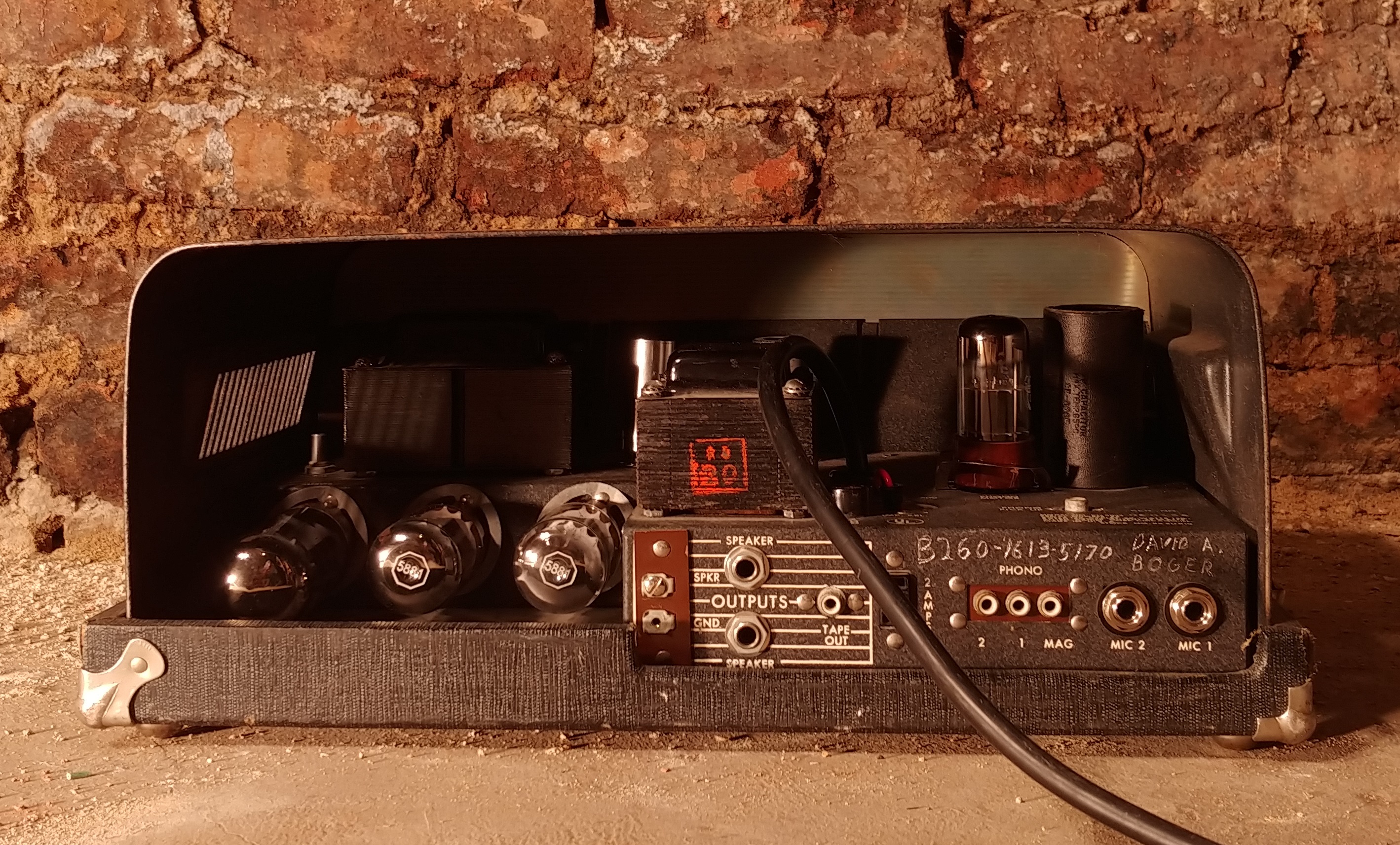
The tubes used are two 12AX7s, one 6SL7, one 6AV6, two 6L6s and one 5U4. Power output is 32 watts. The power amp can be driven to overdrive with as little as 45mV (-30dBV) at maximum volume. This is well within the range of a single coil pickup. This compares to 120mV (-21dBV) for a Deluxe®. With the gain control maxed, the low gain channel overdrives at 45mV (-30dBV) for a mild overdrive. The high gain channel is overdriven at 0.8mV (-65dBV). This compares to 0.34mV (-72dBV) of a Soldano® SLO®. While it has very high gain capabilities, this amplifier is designed around low gain playing. The tube rectifier provides a sweet sustain to your playing.
More pictures and a sound clip are available at https://www.instagram.com/jdpamps/.
For the recording, I used a Les Paul copy straight into the amplifier. The speaker was a single 12″ Jensen Electric Lightning. Recording mic was my phone, an LG V30. Unfortunately, the phone added a bit of compression, so the volume difference between clean and cranked cannot be appreciated in this video.
Hey everyone, I’m excited to reveal a new portion of my webpage called Tech Notes! These are a few of my repairs that I’ve worked on, and what I’ve learned along the way. They’re intended to be informative and helpful, should you run across a similar problem.
Enjoy!
“The Simple Pursuit of Excellence”
–Jason Pittenger
your tube is too big for its clip! It dwarfs the EL34 next to it!
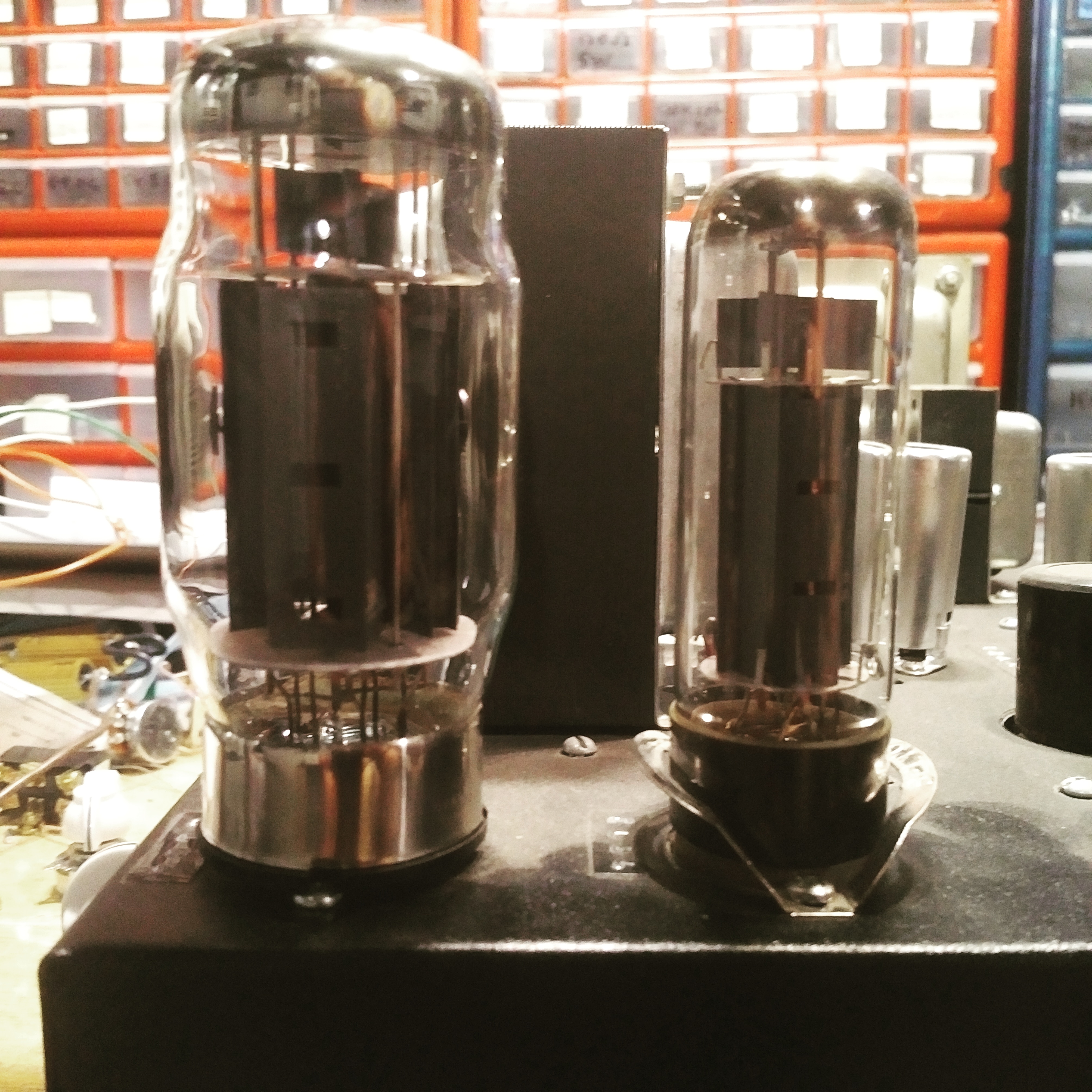
I’m trying out a pair of KT120s. I wanted to evaluate these monsters for a 100 watt amplifier I had in mind. I figured 450V and fixed grid bias would get me just shy of 110 watts. But I only managed 80 watts from a pair.
It looks like they want more voltage. But with higher voltages also comes more expensive parts. I cannot justify their $90/pair price. Especially when I can get 78 watts from a pair of 6L6s at similar voltages. I strive to give my customers the most bang for their buck.
I am sure they are good tubes in their own right, but I don’t think I will be using them for my amplifiers. It’s a shame really, because they look so awesome!
This year has turned out to be a lot more busy than I had expected! I’m back to working on my 50 watt amplifier. The electronics are finished. I am preparing the cab now.
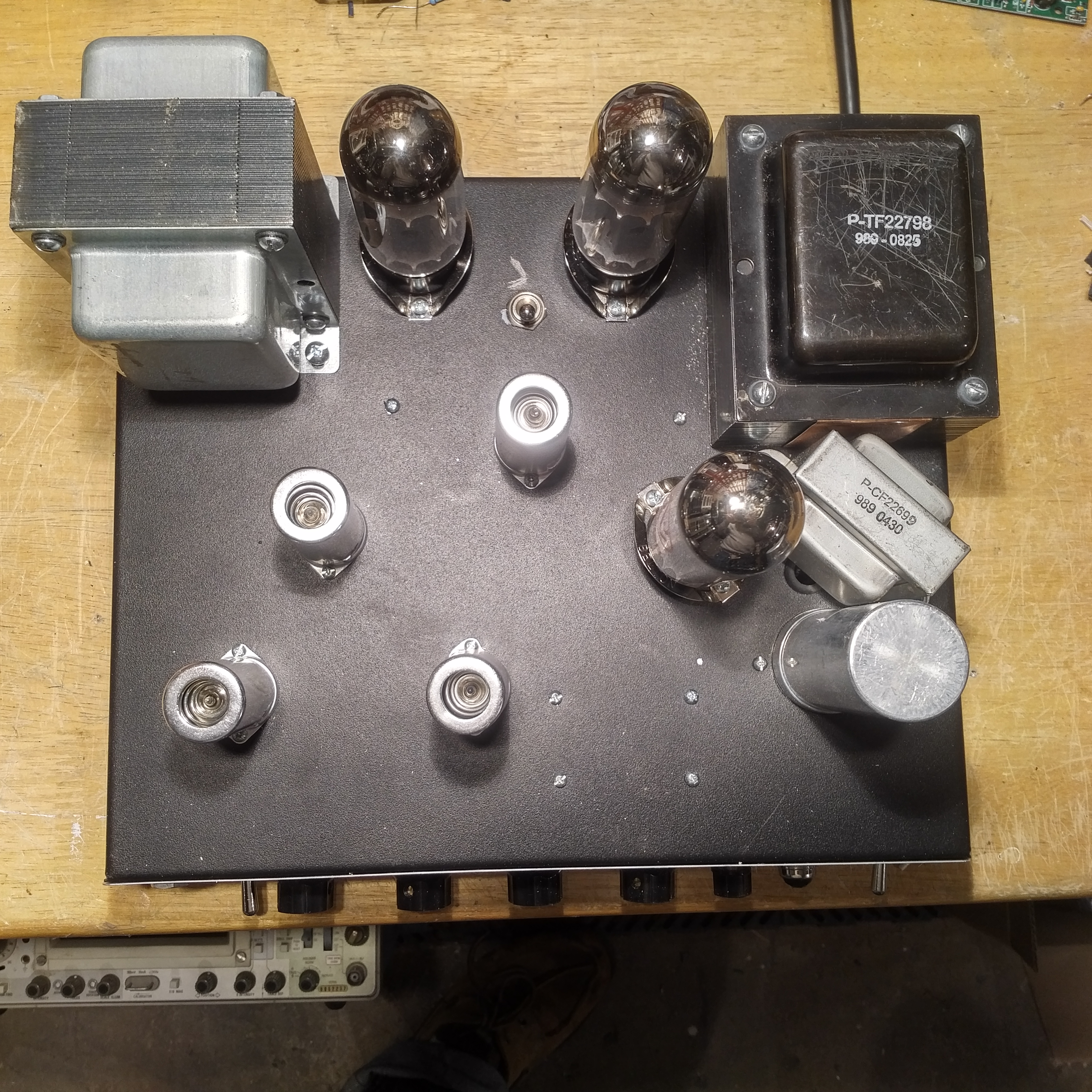
4 x 12AX7s, 1 x 5U4, 2 x 6L6. High/low gain with built in all tube noise gate (high gain only) . Solid State rectifier, tube rectifier, or half of a tube rectifier! 4, 8, 16 ohm. And a special “rabid” mode, that many say sounds like bit crusher…but ALL TUBE! This amplifier can run EL34s, 5881s, 6L6s or even 6V6s.
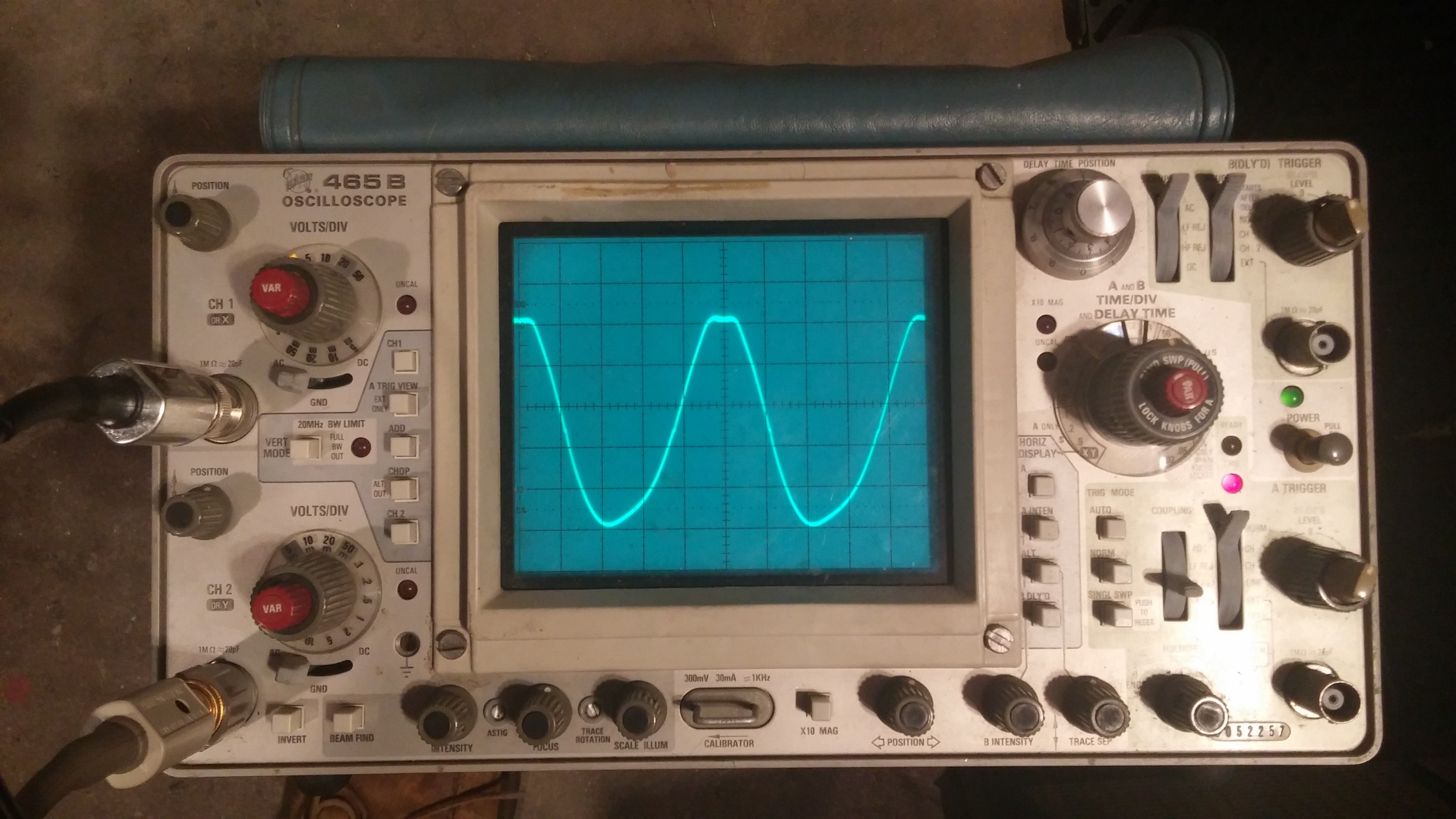
Pictured here is my oscilloscope displaying a 1khz waveform from my 50 watt amplifier. The waveform is noticeably clipped at the top, but just slightly. This was from my output power measurement test. If you’re only interested in the total, scroll to the end of the post. Otherwise, follow along with me.
My amplifier was set up with a 1khz sine wave into the input. The gain knob was increased until clipping, and backed off a bit. The volume knob was then increased until the output was just clipping. The output was driving a 16 ohm dummy load. I measured the voltage that my amplifier was driving across this load.
On screen, you can see the waveform measures 5 divisions high. If you look closely at the 1st input selector switch, it is set to 2 volts per division. The probe is a 10X probe, meaning that the voltage is actually 10X larger than shown on screen. That means this waveform measures 5*2*10 volts or 100 volts peak to peak.
To convert a value from volts peak to peak into volts rms, you must multiply by the square root of 2 (1.41) and divide by 4. This gives you a value of 35.35 volts rms.
At this point, I wanted to do a reality check against my oscilloscope, so I set the frequency of my test signal to 60hz and measured the volts rms with a handheld meter. Why 60hz? The handheld meter is designed for measuring household AC voltages at 60hz.
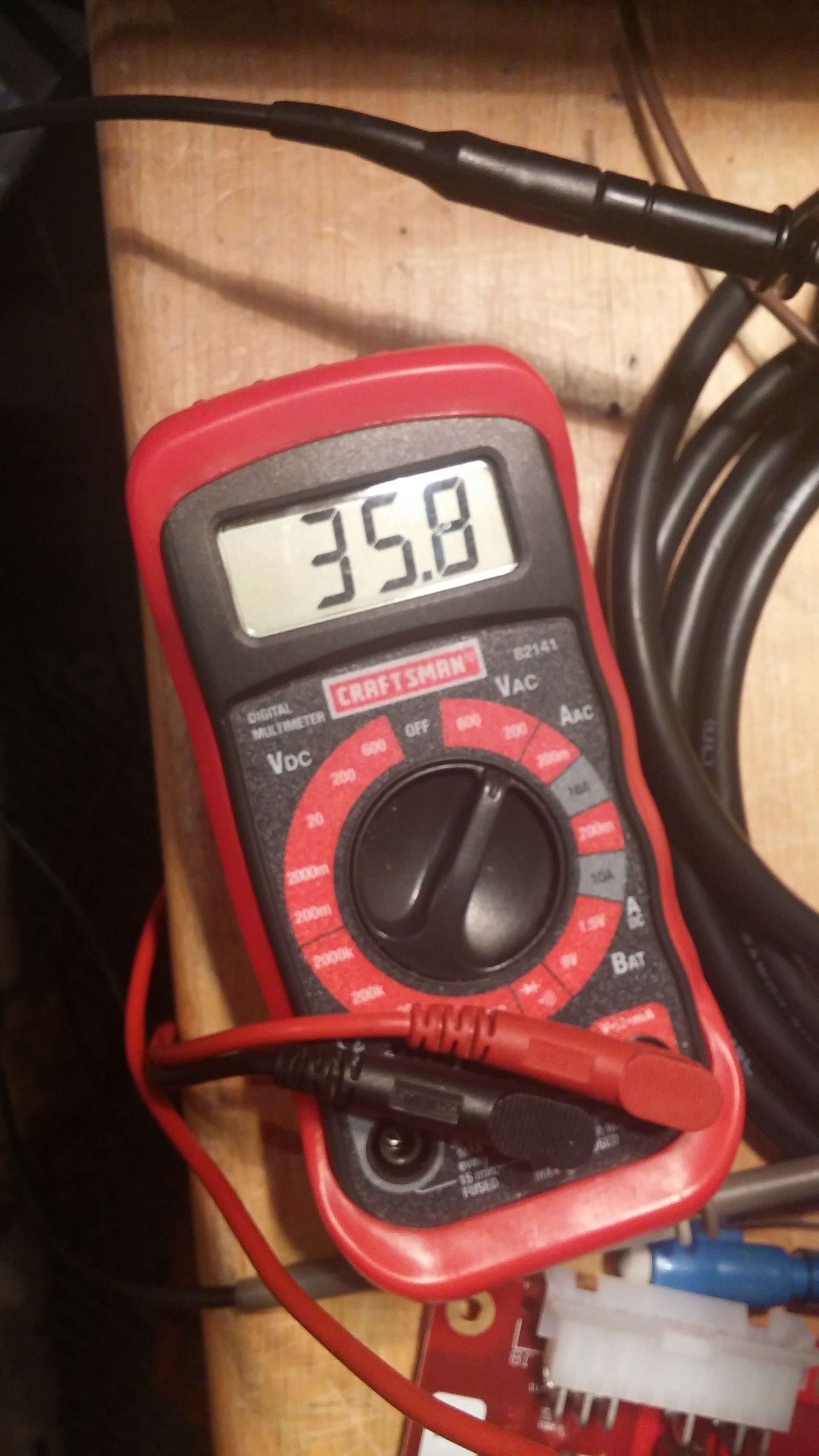
It measures a bit higher than my calculations. This is expected as the meter assumes a perfect sine wave free of any clipping. Nevertheless, it proves my calculations are in the same ballpark.
To convert volts rms into watts rms, you must square the voltage and divide by the load. This gives…
Before I reveal the answer, I want to address the doubts. Some will ask, “Why have the oscilloscope picture measure 1khz, and not 60hz?”. Because this is a fully analog oscilloscope, there was far too much flicker at 60hz to get a good picture. Plus, 1khz is a good high mid frequency where as 60hz is a bass guitar frequency.
“The signal is visibly clipped here. How can you call this ‘clean watts’?” I am measuring the lower peak to the upper peak. Lowering the volume slightly will eliminate the clipping, but wouldn’t change the measurement on the oscilloscope. It serves as a indication that we really are at the limit. It will change the handheld measurement a bit, but it will come to match the oscilloscope measurement when not clipped.
“What percentage T.H.D. are you measuring at?” I don’t know, but I also don’t care. This is a guitar amplifier, not hi-fi. Below this volume, there is no clipping. At and above this point, there is clipping. This is a very good indicator that the sound characteristics change at this power output. Hence, clean power! To go a little further, the fat lower portion of the waveform and the thin upper portion suggests significant 2nd order distortion while clean, imparting a fullness and sweetness to the tone. The clipping on the top peaks (before bottom peaks) indicate asymmetrical clipping (or even order distortion). Both of which are quite musical!
And now the moment you have all been waiting for…I measured an astounding…
78.125 clean watts!!!
All from a pair of 6L6s.

Last week, I had the wonderful opportunity to visit Las Vegas for the 2018 Consumer Electronics Show! It was exciting to see what’s up and coming in the world of electronics! Even though this show is focused on the general consumer, there were a few things specifically for musicians. As you can see above, Gibson had a large tent full of their instruments. Since I was attending as a representative of my daytime employer, I did not have a chance to browse through the Gibson offerings.
I did however, find a small startup company known as.

Fret Zealot makes a guitar training aid designed to mount on any guitar fret board. It’s a small flexible PCB with LEDs under each string, behind every fret wire. It syncs up with a phone app, and uses the LEDs to teach you how to play guitar! It has both common chord positions, and a small library of guitar tabs included. The app plays the songs along with you, at 1/4, 1/2 and full speed! There’s even a large selection of sounds available to match the song you are playing.
I find this worthy of mention here, because it’s the first system I have seen that allows you to use a guitar you already own for this. No longer do you have to purchase a “training” guitar, and have to upgrade later. The adhesive is designed to be removable and not cause damage to the fret board. Any guitar from the Wal-Mart special to a ’67 Stratocastor can become a training guitar. It’s designed to accommodate all major scale lengths. I encourage you to check them out!
2017 is over in two days. It has been an exciting year indeed! My idea went from just an idea, to not one, but two versions. The demonstration was very well received! The prototype exceeded my expectations! I have a little bit of tone adjustments to make, but it is almost complete!
Looking ahead at the year to come, I have exciting goals! For example, today I started gathering information for submitting a patent. This is one of my goals for 2018. Once approved, I plan to launch it as a new product!
This could be an exciting year!
Wishing everyone a Happy New Year!
A few weeks ago, I shared the details of my prototype circuit with a few people, and received some very enthusiastic reactions! Today I am able to give the first private demonstration of a working prototype version…wish me luck!
I have asked the help of another guitarist to lend a hand. I’m hoping to get some positive responses, as well as suggestions for improvements to make this into a marketable product.
Next year I will begin my patent submission, and then I can finally reveal what I’ve been working on! Merry Christmas!
The Simple Pursuit of Excellence
–Jason Pittenger–
